AP4580 Full Bridge MOSFET | High Efficiency Power Management IC
15.00৳
- স্বয়ংক্রিয় PWM/PFM মোড সুইচিং
- কম তাপ উৎপাদন এবং উচ্চ দক্ষতা
- ইন্টিগ্রেটেড MOSFET
- ওভার-কারেন্ট প্রটেকশন (OCP)
- ওভার-ভোল্টেজ প্রটেকশন (OVP)
- শর্ট-সার্কিট প্রটেকশন (SCP)
- লো ড্রপআউট ভোল্টেজ নিয়ন্ত্রণ
In stock
| Package/Size |
SOT-23-8L |
|---|---|
| Transistor Type |
Full Bridge ,N-Channel ,P-Channel |
| Drain Source Voltage (Vdss) |
-20V ,20V |
| Continuous Drain Current (Id) |
-1.3A ,1.5A |
| Power Dissipation (Pd) |
1.4W |
| EasyEDA ID |
C2849569 |
| MFR# |
– |
| Brand |
– |
| Mounting |
– |
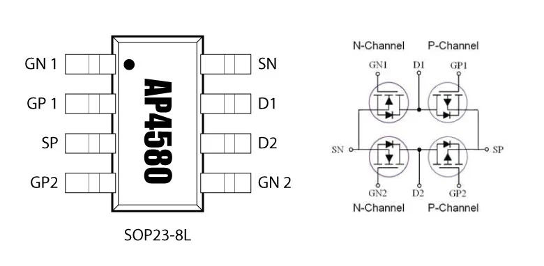
AllPOWER Full Bridge MOSFET : AP4580
AP4580 একটি ফুল-ব্রিজ মস্ফেট চিপ, এটা ভোল্টেজ কন্ট্রোল এবং অপটিমাইজড পাওয়ার ডেলিভারি করতে সক্ষম। এই চিপটি সুনির্দিষ্ট ভোল্টেজ কন্ট্রোল এবং হাই ইফিসিয়েন্সির জন্য ডিজাইন করা হয়েছে, যা সিস্টেমের পাওয়ার কন্সাম্পশন কমাতে সহায়তা করে। এটি সাধারণত মোবাইল চার্জার, পাওয়ার অ্যাডাপ্টার, LED ড্রাইভার ইত্যাদি ইলেকট্রনিক ডিভাইসে ব্যবহৃত হয়।
Simplified Schematic
এর ইন্টিগ্রেটেড MOSFET এবং হাই ইফিসিয়েন্সি সুইচিং টেকনোলজি ব্যবহার করে সর্বোচ্চ পাওয়ার ইফিসিয়েন্সি প্রদান করে। তাছাড়া এটি হাই রেসপন্স টাইম, কম ইলেকট্রোম্যাগনেটিক ইন্টারফারেন্স (EMI), এবং তাপ উৎপাদন কমিয়ে আনে। এর ইন্টেলিজেন্ট প্রটেকশন ফিচার সমূহ যেমন ওভার-কারেন্ট প্রটেকশন (OCP), ওভার-ভোল্টেজ প্রটেকশন (OVP), এবং শর্ট-সার্কিট প্রটেকশন (SCP) অত্যন্ত কার্যকর এবং নির্ভরযোগ্য।
Absolute Maximum Ratings
|
Parameter |
Symbol |
Rating (Max) |
Units |
|
|---|---|---|---|---|
|
N-Channel |
P-Channel |
|||
|
Drain-Source Voltage |
VDS |
20 |
-20 |
V |
|
Gate-Source Voltage |
VGS |
±10 |
±10 |
V |
|
Continuous Drain Current, t<10s VGS@ -10V |
ID@TC=25℃ |
2.0 |
-1.8 |
A |
|
ID@TC=75℃ |
1.5 |
-1.3 |
A |
|
|
PulsedDrain Current1 |
IDM |
12 |
-10 |
A |
|
Total Power Dissipation2 @ TA = 25℃ |
PD |
1.4 |
1.4 |
W |
|
Total Power Dissipation2 @ TA = 75℃ |
1.0 |
0.9 |
W |
|
|
Storage and Junction Temperature Range |
TSTG, TJ |
-55 to 150 |
-55 to 150 |
℃ |
|
Thermal Resistance Junction-ambient1 (t≦10s) |
RθJA |
100 |
100 |
℃/W |
|
130 |
130 |
℃/W |
||
|
Thermal Resistance Junction-case1 |
RθJC |
90 |
90 |
℃/W |
- Repetitive Rating: Pulse width limited by maximum junction temperature
- Surface mounted on FR4 Board, t≦10s
- Pulse Test: Pulse width ≦300µs, Duty Cycle ≦2%
N-Channel Electrical Characteristics (TJ=25 ℃)
|
Parameter |
Symbol |
Conditions |
Min |
Typ |
Max |
Unit |
|---|---|---|---|---|---|---|
|
Drain-Source Breakdown Voltage |
BVDss |
VGS = 0V , ID = 250µA |
20 |
---- |
---- |
V |
|
Static Drain-Source On-Resistance |
RDS(ON) |
VGS = 2.5V , ID = 1.0A |
---- |
70 |
90 |
mΩ |
|
VGS = 4.5V , ID = 2.0A |
---- |
60 |
72 |
mΩ |
||
|
Gate Threshold Voltage |
VGS(th) |
VGS=VDS , ID =-250µA |
0.45 |
0.7 |
1.0 |
V |
|
Drain-Source Leakage Current |
IDSS |
VDS=20V , VGS=0V |
---- |
---- |
1 |
µA |
|
Gate-Source Leakage Current |
IGSS |
VGS=±10V , VDS=0V |
---- |
---- |
±100 |
nA |
|
Forwward Trans-conductance |
gFS |
VDS=5V, ID = 1.5A |
---- |
20 |
---- |
S |
|
Diode Forward Voltage |
VSD |
VGS=0V , IS = 1.0A |
---- |
---- |
1.2 |
V |
|
Continuous Source Current |
IS |
VG=VD=0V, |
---- |
---- |
2.0 |
A |
|
Total Gate Charge |
Qg |
VDS=10V, VGS=6V, ID=2.0A |
---- |
2.7 |
---- |
nC |
|
Gate-Source Charge |
Qgs |
---- |
0.5 |
---- |
||
|
Gate-Drain Charge |
Qgd |
---- |
0.4 |
---- |
||
|
Turn-On Delay Time |
TD(on) |
VDD=10V, VGS=6V, |
---- |
2.3 |
---- |
nS |
|
Rise Time |
Tr |
---- |
3.2 |
---- |
||
|
Turn-Off Delay Time |
TD(off) |
---- |
20 |
---- |
||
|
Fall Time |
Tf |
---- |
3 |
---- |
||
|
Input Capacitance |
CISS |
VDS=10V, VGS=0V, |
---- |
240 |
---- |
pF |
|
Output Capacitance |
COSS |
---- |
45 |
---- |
||
|
Reverse Transfer Capacitance |
CRSS |
---- |
23 |
---- |
P-Channel Electrical Characteristics (TJ=25 ℃)
|
Parameter |
Symbol |
Conditions |
Min |
Typ |
Max |
Unit |
|---|---|---|---|---|---|---|
|
Drain-Source Breakdown Voltage |
BVDss |
VGS = 0V , ID = -250µA |
-20 |
---- |
---- |
V |
|
Static Drain-Source On-Resistance |
RDS(ON) |
VGS = -2.5V , ID = -1.0A |
---- |
190 |
220 |
mΩ |
|
VGS = -4.5V , ID = -1.8A |
---- |
128 |
146 |
mΩ |
||
|
Gate Threshold Voltage |
VGS(th) |
VGS=VDS , ID =-250µA |
-0.45 |
0.7 |
-1.0 |
V |
|
Drain-Source Leakage Current |
IDSS |
VDS= -20V , VGS=0V |
---- |
---- |
-1 |
µA |
|
Gate-Source Leakage Current |
IGSS |
VGS=±10V , VDS=0V |
---- |
---- |
±100 |
nA |
|
Forwward Trans-conductance |
gFS |
VDS= -5V, ID = -1.0A |
---- |
15 |
---- |
S |
|
Diode Forward Voltage |
VSD |
VGS=0V , IS = -1.0A |
---- |
---- |
-1.2 |
V |
|
Continuous Source Current |
IS |
VG=VD=0V, |
---- |
---- |
-1.8 |
A |
|
Total Gate Charge |
Qg |
VDS=-10V, VGS= -6V, |
---- |
3.0 |
---- |
nC |
|
Gate-Source Charge |
Qgs |
---- |
0.5 |
---- |
||
|
Gate-Drain Charge |
Qgd |
---- |
0.8 |
---- |
||
|
Turn-On Delay Time |
TD(on) |
VDD= -10V, VGS= -6V, |
---- |
9.5 |
---- |
nS |
|
Rise Time |
Tr |
---- |
4.9 |
---- |
||
|
Turn-Off Delay Time |
TD(off) |
---- |
21.5 |
---- |
||
|
Fall Time |
Tf |
---- |
10 |
---- |
||
|
Input Capacitance |
CISS |
VDS= -10V, VGS= 0V, |
---- |
290 |
---- |
pF |
|
Output Capacitance |
COSS |
---- |
100 |
---- |
||
|
Reverse Transfer Capacitance |
CRSS |
---- |
34 |
---- |
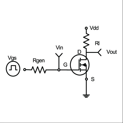
Figure 1: Switching test circuit
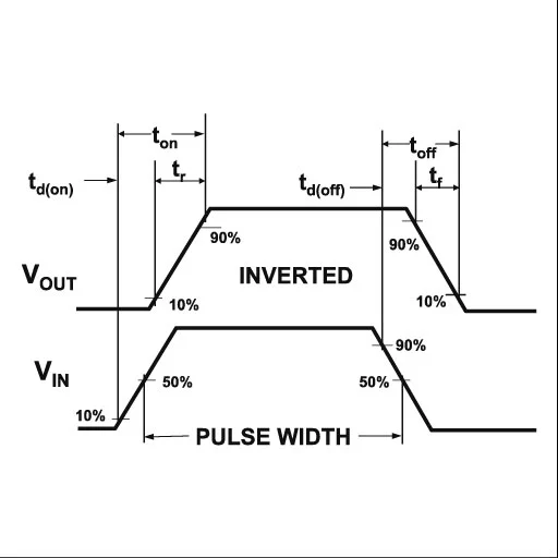
Figure 2: Switching Waveforms of AP4580
Table Of Contents
FAQs and Answers
The AP4580 MOSFET is primarily designed for power management in devices like mobile chargers, LED drivers, and DC-DC converters.
Yes, the AP4580 MOSFET includes over-current protection (OCP) to ensure safe operation in high-power environments.
The AP4580 MOSFET is designed for high energy efficiency, minimizing power loss and heat generation.
It includes multiple safety features such as over-current protection (OCP), over-voltage protection (OVP), and short-circuit protection (SCP).
Reference
Only logged in customers who have purchased this product may leave a review.


 LED
LED TVS
TVS Microphones





Reviews
There are no reviews yet.