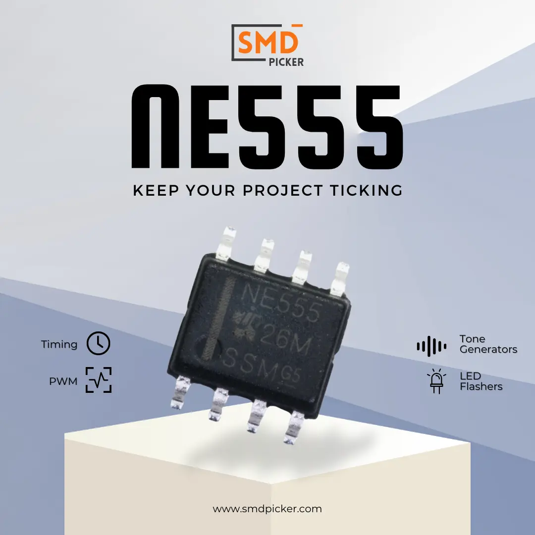
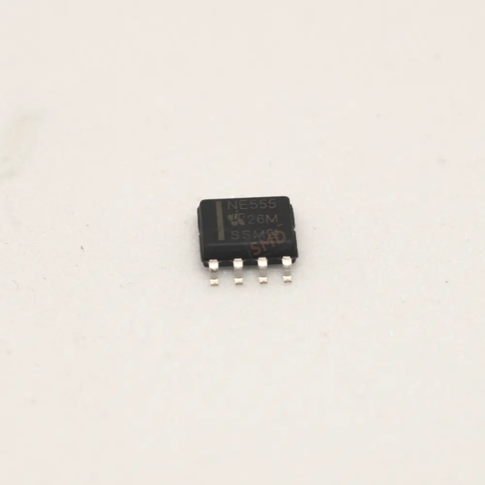
NE555 Timer IC: Master Time Controller in SOP-8 Package
9.84৳ Original price was: 9.84৳ .9.80৳ Current price is: 9.80৳ .Pcs
NE555 timer IC is a popular integrated circuit used for creating precise time delays and oscillations. It’s easy to use and works in different modes, making it perfect for various electronics projects, from simple to complex.
In stock
| Brand |
IDCHIP |
|---|---|
| Operating Voltage Range |
4.5V ~ 16V |
| Package/Size |
SOP-8 |
| EasyEDA ID |
– |
| MFR# |
– |
| Mounting |
SMD/SMT |
The NE555 Timer IC
Discover the power of the NE555 Timer IC, a versatile integrated circuit that unlocks precise time delays and oscillations. Whether you're a beginner or an experienced electronics enthusiast, this blog post will guide you through the world of NE555, sharing insights on its functionality, modes, and how it can bring your electronics projects to life. Join us on this exciting journey and gain the skills to create awe-inspiring circuits with ease. Start exploring the limitless possibilities today!
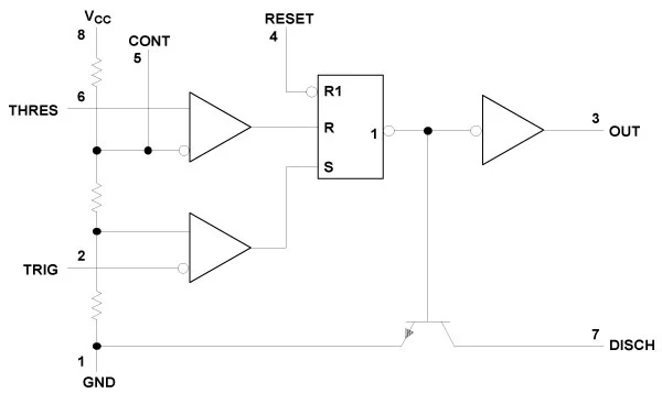
Simplified Schematic
NE555 Timer IC is monolithic timing circuits capable of producing accurate time delays or oscillation. Inthe time delay mode of operation, the timed interval is controlled by a single external resistor and capacit or network. In the astable mode of operation, the frequency and duty cycle may be independently controlled with two external resistors and a single external capacitor.
Pin Functions
|
PIN |
Name |
Mode |
DESCRIPTION |
|---|---|---|---|
|
1 |
GND |
--- |
Ground |
|
2 |
TRIG |
I |
Start of timing input. TRIG < ½ CONT sets output high and discharge open |
|
3 |
OUT |
O |
High current timer output signal |
|
4 |
RESET |
I |
Active low reset input forces output and discharge low |
|
5 |
CONT |
I/O |
Controls comparator thresholds, Outputs 2/3 VCC, allows bypass capacitor connection |
|
6 |
THRES |
I |
End of timing input. THRES > CONT sets output low and discharge low |
|
7 |
DISCH |
O |
Open collector output to discharge timing capacitor |
|
8 |
VCC |
--- |
Input supply voltage, 4.5 V to 16 V. |
Absolute Maximum Ratings
|
Parameter |
Min |
Max |
Units |
|---|---|---|---|
|
Supply Voltage, VCC |
4.5 |
16 |
V |
|
Input Voltage (control, reset, threshold and trigger) |
VCC | ||
|
Output Current, I0 |
±200 |
mA |
|
|
Operating Free-Air Temperature, TA |
70 |
°C |
|
|
Storage Temperature Range, TSTG |
-65 |
+150 |
Functional Modes
Monostable Operation
The NE555 timer IC in monostable mode is a powerful tool for creating reliable and accurate time delays in a variety of electronic circuits. For instance, if you need a 1-second pulse, you might choose R = 909kΩ and C = 1µF (since 1.1 × 909kΩ × 1µF ≈ 1 second).
It's monostable operation mode is used to create a one-shot pulse. Monostable mode is used for generating precise time delays and single pulses in response to an input trigger, It's also used in debouncing mechanical switches to eliminate noise and false triggers. As a timmer the NE-555 is useful in applications requiring a precise time delay, such as timers and time-based controls. Here’s a summary of how it works:
- Triggering: In monostable mode, NE555 Timer IC is triggered by a negative pulse applied to its trigger pin (pin 2). This pulse must be shorter than the desired output pulse.
- Output: When triggered, the output pin (pin 3) goes high for a period determined by an external resistor (R) and capacitor (C). After this period, the output returns to its low state.
-
Timing: The duration of the output high pulse is given by the formula:
𝑇
=
1.1
×
𝑅
×
𝐶
T=1.1×R×C
where 𝑇 T is the time in seconds, 𝑅 R is the resistance in ohms, and 𝐶 C is the capacitance in farads. - Reset: The output pulse can be interrupted and reset by applying a low signal to the reset pin (pin 4).
Astable Operation
The NE-555 Timer IC in astable mode is a reliable and versatile solution for generating continuous square waves and oscillations in various electronic applications like, Clock Generators, LED Flashers, Tone Generators, Pulse Width Modulation (PWM) etc.
Astable mode is used to generate continuous square waves or oscillations. Here’s an overview of how it works:
- Continuous Oscillation: In astable mode, the NE555 Timer IC continuously switches between its high and low states, generating a square wave output.
- No External Trigger: Unlike monostable mode, astable mode does not require an external trigger to start the oscillation.
- Frequency and Duty Cycle: The frequency and duty cycle of the output waveform are determined by two external resistors (R1 and R2) and a capacitor (C).
- Frequency (f): The frequency of the oscillation is given by: 𝑓 = 1.44 / ((𝑅1+2𝑅2)×𝐶)
- Duty Cycle (D): The duty cycle, which is the ratio of the high time to the total period, can be calculated as: 𝐷 = 𝑅2 / (𝑅1+2𝑅2)
FAQ about NE-555 Ic
The NE555 Timer IC is an integrated circuit used for generating precise time delays or oscillations. It can operate in monostable, astable, and bistable modes.
The primary operating modes are:
- Monostable mode: Generates a single pulse when triggered.
- Astable mode: Generates continuous square wave oscillations.
- Bistable mode: Operates as a flip-flop, switching between two stable states.
In monostable mode, the NE555 produces a single output pulse of a fixed duration when triggered by an external signal. The pulse duration is determined by an external resistor and capacitor.
In astable mode, the NE555 generates a continuous square wave output. The frequency and duty cycle of the oscillation are set by two external resistors and a capacitor.
You need a resistor and a capacitor to set the pulse duration, along with a power supply and a trigger input signal.
Common applications include:
- Timers
- Pulse generation
- LED flashers
- Clock generators
- Tone generation
- Pulse width modulation (PWM)
The NE555 timer IC can operate up to a few hundred kilohertz, but for higher frequencies, specialized timer ICs or oscillators may be more suitable.
The NE555 timer IC typically operates with a power supply voltage range of 4.5V to 15V.
To improve stability, you can add a capacitor (usually 0.01µF) between the control voltage pin (pin 5) and ground.
The discharge pin is used to discharge the timing capacitor in astable and monostable modes, helping to control the timing intervals.
Yes, there are low-power versions like the TLC555, which are suitable for battery-operated applications and have lower power consumption.
The NE555 timer IC can source or sink up to 200mA, but for higher currents, an external transistor or MOSFET should be used to drive the load.
Reference
Table Of Contents
Only logged in customers who have purchased this product may leave a review.


 LED
LED TVS
TVS Microphones


Reviews
There are no reviews yet.