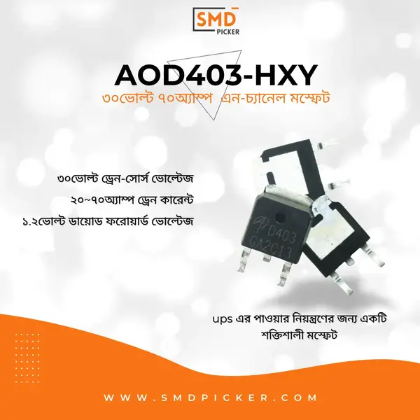
HXY70P03D MOSFET – High-Efficiency P-Channel Power MOSFET AOD403-HXY
25.00৳
- Drain-Source Voltage (Vds): -30V
- Continuous Drain Current (Id): -70A
- Gate-Source Voltage (Vgs): ±20V
- Low Rds(on): 8-10 mΩ at Vgs = -10V
- High Power Dissipation: Up to 150W (depending on package)
- Fast Switching Speed
- Operating Temperature Range: -55°C to +175°C
In stock
HXY70P03D AOD403-HXY MOSFET
The HXY70P03D MOSFET is a high-performance P-channel MOSFET designed to meet the demands of modern power management and switching applications. With its low on-resistance, high current capability, and robust design, the HXY70P03D is an ideal choice for engineers and designers looking to optimize the efficiency and reliability of their electronic circuits. It's also marked as AOD403-HXY.
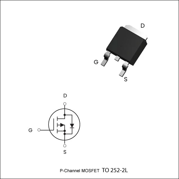
Simplified Schematic
The HXY70P03D MOSFET is engineered for excellence in performance and durability. Whether you're designing power supplies, motor drivers, or DC-DC converters, this P-channel MOSFET provides the reliability and efficiency needed to drive high-current loads with minimal power loss. Its low on-resistance reduces conduction losses, while its high current capability ensures that even the most demanding applications can be handled with ease.
Absolute Maximum Ratings
|
Symbol |
Parameter |
Rating |
Units |
|---|---|---|---|
| VDS |
Drain-Source Voltage |
-30 |
V |
| VGS |
Gate-Source Voltage |
±20 |
V |
| ID@TC=25℃ | Continuous Drain Current, VGS@ -10V1,6 |
-70 |
A |
| ID@TC=100℃ | Continuous Drain Current, VGS@ -10V1,6 |
-50 |
A |
| IDM | PulsedDrain Current2 |
-200 |
A |
|
EAS |
Single PulseAvalanche Energy3 |
80 |
mJ |
| IAS | Avalanche Current |
-40 |
A |
| PD@TC=25℃ | Total Power Dissipation4 |
90 |
W |
| TSTG |
Storage Temperature Range |
-55 to 175 |
℃ |
| TJ |
Operating Junction Temperature Range |
-55 to 175 |
℃ |
| RθJA | Thermal Resistance Junction-ambient 1(t≦10S) |
20 |
℃/W |
| Thermal Resistance Junction-ambient 1(Steady State) |
50 |
℃/W |
|
|
RθJC |
Thermal Resistance Junction-case1 |
1.6 |
℃/W |
Electrical Characteristics (TJ=25 ℃, unless otherwise noted)
|
Symbol |
Parameter |
Conditions |
Min |
Typ |
Max |
Unit |
|---|---|---|---|---|---|---|
| BVDss |
Drain-Source Breakdown Voltage |
VGS=0V , ID=-250uA |
-30 |
---- |
---- |
V |
| RDS(ON) | Static Drain-Source On-Resistance2 |
VGS=-10V , ID=-20A |
---- |
7 |
10 |
mΩ |
| VGS=-4.5V , ID=-15A |
---- |
11 |
18 |
mΩ |
||
|
VGS(th) |
Gate Threshold Voltage |
VGS=VDS , ID =-250uA |
-1.2 |
---- |
-2.5 |
V |
|
IDSS |
Drain-Source Leakage Current |
VDS=-24V , VGS=0V , TJ=25℃ |
---- |
---- |
-1 |
uA |
|
VDS=-24V , VGS=0V , TJ=55℃ |
---- |
---- |
-5 |
|||
|
IGSS |
Gate-Source Leakage Current |
VGS=±20V , VDS=0V |
---- |
---- |
±100 |
nA |
|
Rg |
Gate Resistance |
VDS=0V , VGS=0V , f=1MHz |
---- |
1.2 |
---- |
Ω |
|
Qg |
Total Gate Charge (-10V) |
VDS=-15V, VGS=-10V, ID=-18A |
---- |
60 |
---- |
nC |
|
Qgs |
Gate-Source Charge |
---- |
9 |
---- |
||
|
Qgd |
Gate-Drain Charge |
---- |
15 |
---- |
||
|
Td(on) |
Turn-On Delay Time |
VDD=-15V, VGS=-10V, |
---- |
17 |
---- |
nS |
|
Tr |
Rise Time |
---- |
40 |
---- |
||
|
Td(off) |
Turn-Off Delay Time |
---- |
55 |
---- |
||
|
Tf |
Fall Time |
---- |
13 |
---- |
||
|
CISS |
Input Capacitance |
VDS=-25V , VGS=0V , f=1MHz |
---- |
3450 |
---- |
pF |
|
COSS |
Output Capacitance |
---- |
255 |
---- |
||
|
CRSS |
Reverse Transfer Capacitance |
---- |
140 |
---- |
||
|
IS |
VG=VD=0V , Force Current |
---- |
---- |
-70 |
A |
|
|
VSD |
Diode Forward Voltage2 |
VGS=0V , IS=-1A , TJ=25℃ |
---- |
---- |
-1.2 |
V |
|
TRR |
Reverse Recovery Time |
IF=-20A , di/dt=100A/µs, TJ=25℃ |
---- |
22 |
---- |
nS |
|
QRR |
Reverse Recovery Charge |
---- |
72 |
---- |
nC |
Note :
- The data tested by surface mounted on a 1 inch2 FR-4 board with 2OZ copper.
- The data tested by pulsed , pulse width ≦ 300us , duty cycle ≦ 2%.
- The EAS data shows Max. rating . The test condition is VDD=-50V,VGS=-10V,L=0.1mH,IAS=-40A.
- The power dissipation is limited by 150℃ junction temperature.
- The data is theoretically the same as ID and IDM , in real applications , should be limited by total power dissipation.
- The maximum current rating is package limited.
FAQ about NE-555 Ic
The maximum drain-source voltage (Vds) for the HXY70P03D is -30V.
The HXY70P03D can handle a continuous drain current (Id) of up to -70A at 25°C.
The typical on-resistance (Rds(on)) of the HXY70P03D is between 8 to 10 mΩ when the gate-source voltage (Vgs) is -10V.
Yes, the HXY70P03D is designed to operate within a temperature range of -55°C to +175°C, making it suitable for various environmental conditions.
Absolutely. The HXY70P03D's high efficiency and robust design make it an excellent choice for inverter circuits, including those used in solar power systems.
Reference
Table Of Contents
| Brand |
HXY MOSFET |
|---|---|
| Package/Size |
TO-252-2L |
| Transistor Channel |
P-Channel |
| Drain Source Voltage (Vdss) |
30v |
| Continuous Drain Current (Id) |
70A |
| Power Dissipation (Pd) |
90W |
| EasyEDA ID |
C4748761 |
| MFR# |
– |
| Mounting |
– |
You must be logged in to post a review.


 LED
LED TVS
TVS Microphones


Reviews
There are no reviews yet.