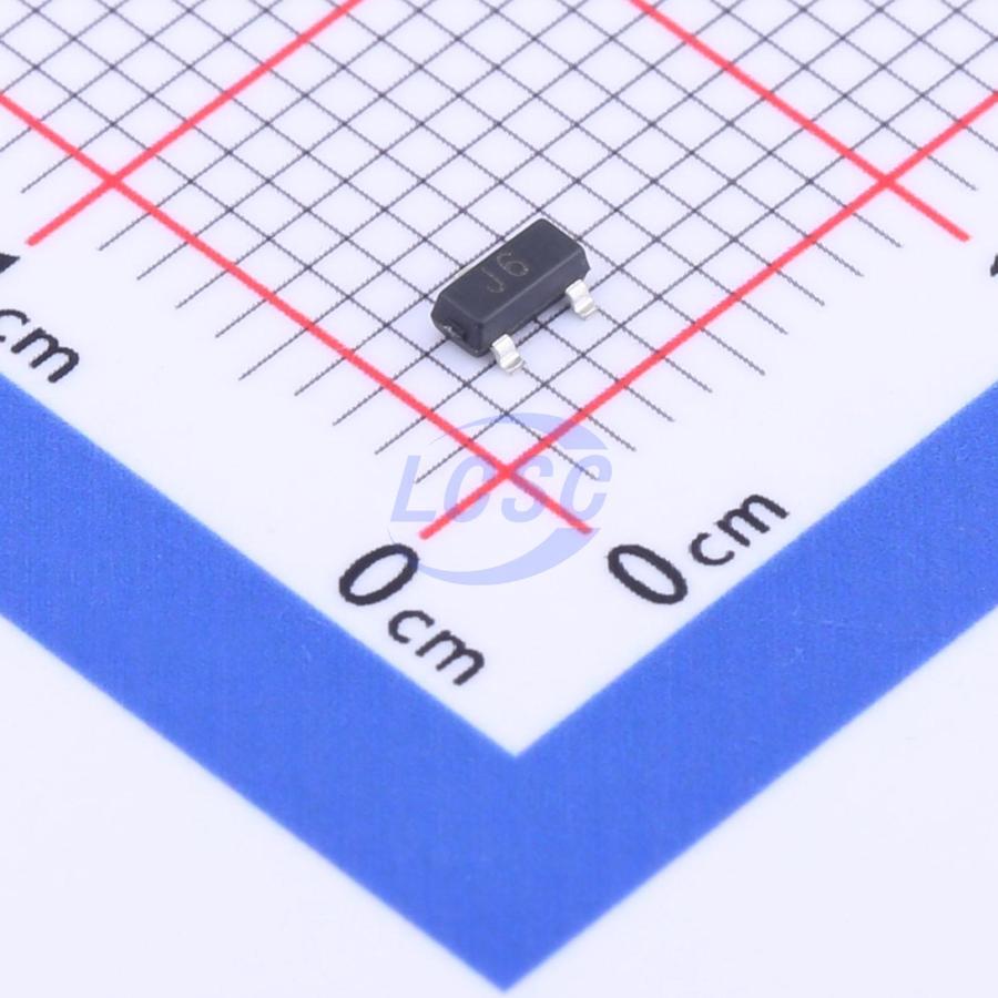
S9014 BjT – 45V 100mA NPN Bipolar Transistors
2.25৳
45V 200mW 300@1mA,5V 100mA NPN SOT-23 Bipolar (BJT)
In stock
| Brand |
HXY MOSFET |
|---|---|
| Package/Size |
SOT-23 |
| Collector-Emitter Breakdown Voltage (Vceo) |
45V |
| Power Dissipation (Pd) |
200mW |
| EasyEDA ID |
C920324 |
| MFR# |
– |
| Mounting |
SMD/SMT |
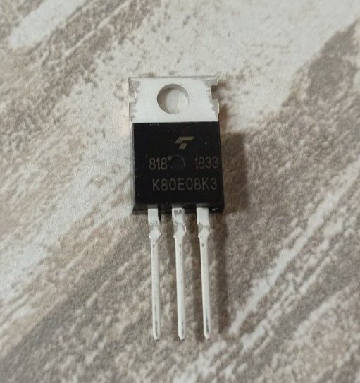
VBZM150N03 N-Channel 30V (D-S) MOSFET
Simplified Schematic
VBZM150N03 একটি হাই কুয়ালিটি N-Channel MOSFET যা 30VDS ড্রেন সোর্স ভোল্টেজ এবং 140A পর্যন্ত ড্রেন কারেন্ট সাপোর্ট করে। এর গেট-সোর্স ভোল্টেজ (VGS) ±20V পর্যন্ত সহ্য করতে পারে, যা কন্ট্রোলিং এবং ড্রাইভিং সার্কিটের স্থায়িত্ব নিশ্চিত করে এবং ইন্সট্যান্টেনিয়াস লোডের ক্ষেত্রে খুবই উপযোগী।
Absolute Maximum Ratings
|
Parameter |
Symbol |
Rating (Max) |
Units |
|
|---|---|---|---|---|
|
Drain-Source Voltage |
VDS |
30 |
V |
|
|
Gate-Source Voltage |
VGS |
±10 |
||
|
Continuous Drain Current, (TJ =175℃) |
TC=25℃ |
ID |
140 a, e |
A |
|
TC=70℃ |
110e | |||
|
TA=25℃ |
39b, c | |||
|
TA=70℃ |
28b, c | |||
|
Continuous Source-Drain Diode Current |
TC=25℃ |
IS |
||
|
TA=25℃ |
||||
|
Pulsed Drain Current |
IDM |
370 |
||
|
Avalanche Current Pulse |
L = 0.1 mH |
IAS |
39 |
|
|
Single Pulse Avalanche Energy |
EAS |
375 |
mJ |
|
|
Maximum Power Dissipation |
TC=25℃ |
PD |
250a |
W |
|
TC=70℃ |
175 |
|||
|
TA=25℃ |
||||
|
TA=70℃ |
||||
|
Storage and Junction Temperature Range |
TSTG, TJ |
-55 to 175 |
℃ |
|
এগুলো শুধুমাত্র স্ট্রেস রেটিং। এর বেশি হলে মস্ফেটটি পুড়ে যেতে পারে।
Specifications of VBZM150N03 MOSFET
|
Parameter |
Symbol |
Test Conditions |
Min |
Typ. |
Max |
Unit |
|---|---|---|---|---|---|---|
|
Drain-Source Breakdown Voltage |
VDS |
VGS = 0 V, ID = 250 µA |
30 |
---- |
---- |
V |
|
Temperature Coefficient |
∆VDS/TJ |
ID = 250 µA |
---- |
35 |
---- |
mV/°C |
|
Temperature Coefficient |
∆VGS/TJ |
---- |
-7.5 |
---- |
||
|
Gate-Source Threshold Voltage |
VGS(th) |
VDS = VGS, ID = 250 µA |
1.0 |
---- |
3.0 |
V |
|
Gate-Source Leakage |
IGSS |
VDS = 0 V, VGS = ± 20 V |
---- |
---- |
±100 |
nA |
|
Zero Gate Voltage Drain Current |
IDSS |
VDS = 0 V, VGS = ± 20 V |
---- |
---- |
1 |
µA |
|
VDS = 24 VGS = 0 V, TJ = 55 °C |
---- |
---- |
10 |
|||
|
On-State Drain Currentf |
ID(on) |
VDS ≥5 V, VGS = 10 V |
90 |
---- |
---- |
A |
|
Forward Transconductanceg |
gFS |
VDS = 15 V, ID = 38.8 A |
---- |
160 |
---- |
S |
|
Drain-Source On-State Resistancef |
RDS(on) |
VGS = 10 V, ID = 38.8 A |
---- |
0.0020 |
---- |
Ω |
|
VGS = 4.5 V, ID = 37 A |
0.0028 |
|
Parameter |
Symbol |
Test Conditions |
Min |
Typ |
Max |
Unit |
|---|---|---|---|---|---|---|
|
Input Capacitance |
CISS |
VDS = 15 V, VGS = 0 V, f = 1 MHz |
---- |
8400 |
---- |
pF |
|
Output Capacitance |
COSS |
---- |
1725 |
---- |
||
|
Reverse Transfer Capacitance |
CRSS |
---- |
970 |
---- |
||
|
Total Gate Charge |
QG |
VDS = 15 V, VGS = 10 V, ID = 38.8 A |
---- |
171 |
257 |
nC |
|
VDS = 15 V, VGS = 4.5 V, ID = 28.8 A |
---- |
81.5 |
123 |
|||
|
Gate-Source Charge |
QGS |
---- |
34 |
---- |
||
|
Gate-Drain Charge |
QGD |
---- |
29 |
---- |
||
|
Gate Resistance |
RG |
f = 1 MHz |
---- |
1.4 |
2.1 |
Ω |
|
Turn-On Delay Time |
tD(on) |
VDD = 15 V, RL = 0.625 Ω ID ≅ 24 A, VGEN = 10 V, Rg = 1 Ω |
---- |
18 |
27 |
nS |
|
Rise Time |
tR |
11 |
17 |
|||
|
Turn-Off Delay Time |
tD(off) |
70 |
105 |
|||
|
Fall Time |
tF |
10 |
15 |
|||
|
Turn-On Delay Time |
tD(on) |
VDD = 15 V, RL = 0.67 Ω ID ≅ 22.5 A, VGEN = 4.5 V, Rg = 1 Ω |
---- |
55 |
83 |
|
|
Rise Time |
tR |
180 |
270 |
|||
|
Turn-Off Delay Time |
tD(off) |
55 |
83 |
|||
|
Fall Time |
tF |
12 |
18 |
|
Parameter |
Symbol |
Test Conditions |
Min |
Typ |
Max |
Unit |
|---|---|---|---|---|---|---|
|
Input Capacitance |
CISS |
TC = 25°C |
---- |
140 |
---- |
A |
|
Pulse Diode Forward Currentf |
ISM |
---- |
---- |
370 |
---- |
|
|
Body Diode Voltage |
VSD |
IS = 22A |
---- |
0.8 |
---- |
V |
|
Body Diode Reverse Recovery Time |
tRR |
IF = 20 A, di/dt = 100 A/µs, TJ = 25 °C |
---- |
52 |
78 |
nS |
|
Body Diode Reverse Recovery Charge |
QRR |
---- |
70.2 |
105 |
nC |
|
|
Reverse Recovery Fall Time |
tRRF |
---- |
27 |
---- |
nS |
|
|
Reverse Recovery Rise Time |
tRRR |
---- |
25 |
---- |
Thermal Resistance Ratings
Note:
- Based on TC = 25 °C.
- Surface mounted on 1" x 1" FR4 board.
- t = 10 sec.
- Maximum under steady state conditions is 90 °C/W.
- Calculated based on maximum junction temperature. Package limitation current is 90 A.
- Pulse test; pulse width ≤ 300 µs, duty cycle ≤ 2%.
- Guaranteed by design, not subject to production testing.

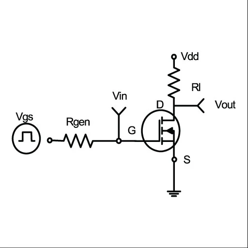
Figure 1: Switching test circuit

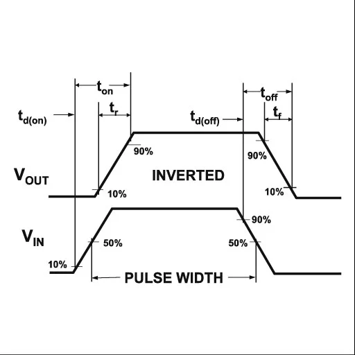
Figure 2: Switching Waveforms of AP4580
Table Of Contents
FAQs and Answers
The VBZM150N03 MOSFET has a Drain-Source voltage rating of 30V.
The maximum continuous drain current for the VBZM150N03 is 140A, making it suitable for high-power applications.
The RDS(on) value of the VBZM150N03 is 0.0020Ω when the Gate-Source voltage (VGS) is 10V.
The VBZM150N03 MOSFET is ideal for use in applications such as DC/DC Converters, Server Power Systems, OR-ing, UPS, IPS and Power Supply.
The VBZM150N03 MOSFET has an operating temperature range of -55°C to +175°C, ensuring reliable performance in a wide range of environments.
Reference
Only logged in customers who have purchased this product may leave a review.


 LED
LED TVS
TVS Microphones


Reviews
There are no reviews yet.